
Flange CAD Drawing Generator
Describe a pipe, motor, weld-neck, or clamp flange with its bore, bolt circle, face, and hub geometry. DrawCAD produces a CAD-style image for visual planning and communication.
Çıktı: CAD tarzında PNG · Düzenlenemez CAD dosyası

How to generate a flange drawing
Flange drawing prompts
Choose a flange construction, then set its main diameters, hole pattern, sealing face, and preferred technical view.
 Flange type: raised-faceOutside diameter: 120mmBore diameter: 55mmFlange thickness: 16mmBolt count: 6holes
Concept dimensions guide the prompt and visual only; they are not manufacturable CAD geometry or production drawings.
Configure a flange drawing
More parameters
Oluşturulan ipucu
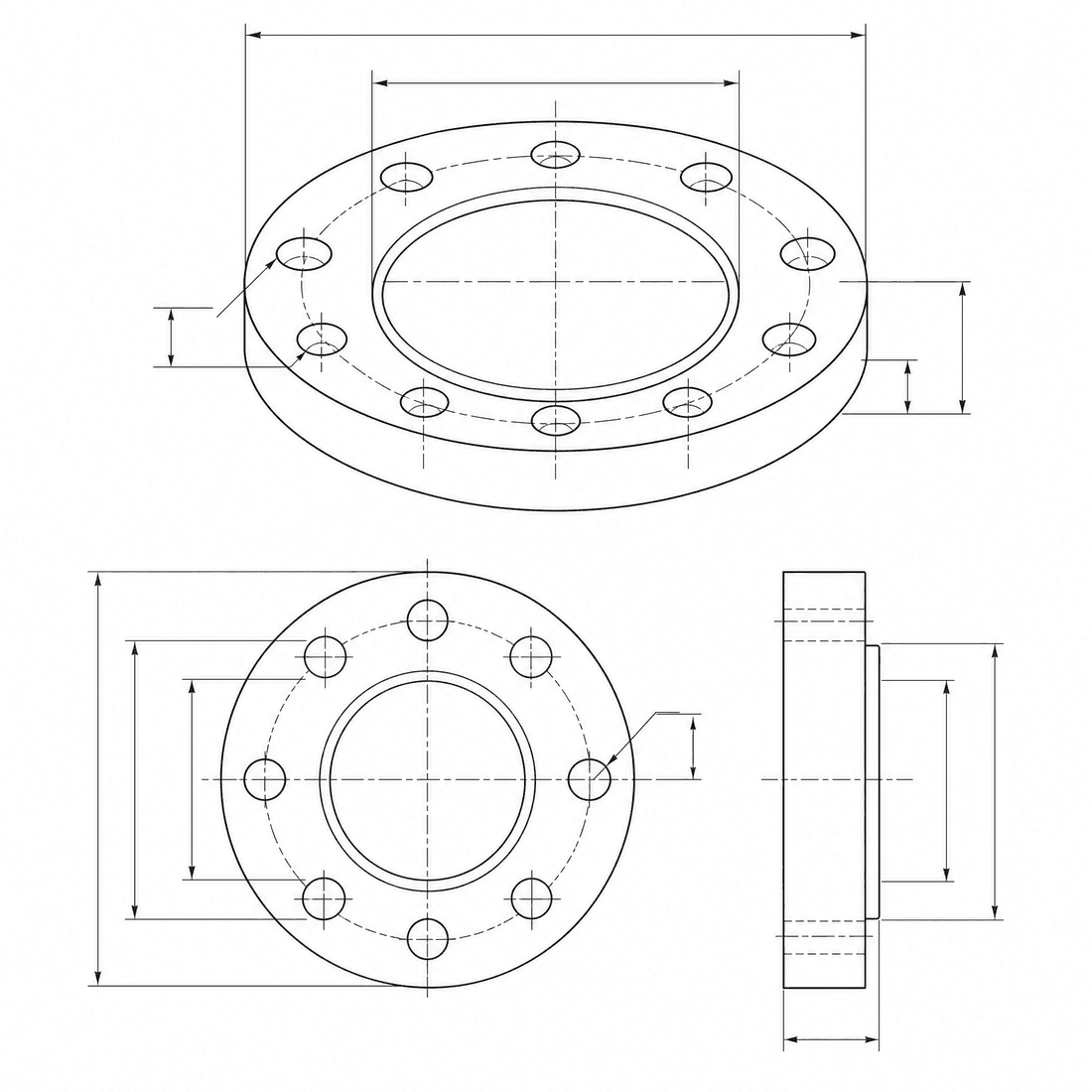
Create a dimensioned CAD-style technical drawing of a flange, with a front view, axial section, isometric view, centerlines, diameter symbols, and a fully defined bolt-circle pattern. circular raised-face pipe flange with a concentric gasket land. Outside diameter: 120mm. Bore diameter: 55mm. Flange thickness: 16mm. Bolt count: 6holes. Bolt-circle diameter: 90mm. Bolt-hole diameter: 11mm.
Flange CAD-style examples
Sık Sorulan Sorular
Can DrawCAD select a standard flange size?
No. You can name a standard for visual context, but pressure class, dimensions, materials, and compliance must be checked against the authoritative specification.
How should I describe a bolt circle?
Include the number of equally spaced holes, each hole diameter, the pitch-circle diameter, and any angular offset from a centerline.
Is the result suitable for flange fabrication?
No. It is a CAD-style image, not a toleranced manufacturing drawing or verified STEP/STL file. Sealing, pressure, and fabrication details require engineering CAD and review.
Daha fazla oluşturma denemesi mi gerekiyor?
Yükseltme yaptıktan sonra daha fazla puan, daha yüksek çözünürlük ve filigran içermeyen dışa aktarma imkanına sahip olacaksınız.