
Heatsink CAD Drawing Generator
Describe fin pitch, fin height, base thickness, and the mounting pattern, and DrawCAD renders a clean CAD-style heatsink image for thermal concept reviews, datasheets, and enclosure airflow studies.
Salida: CAD estilo PNG · No es un archivo editable CAD
How to generate a heatsink drawing
Heatsink drawing prompts
Pick a fin architecture first, then swap in your own footprint, fin count, pitch, and mounting interface.
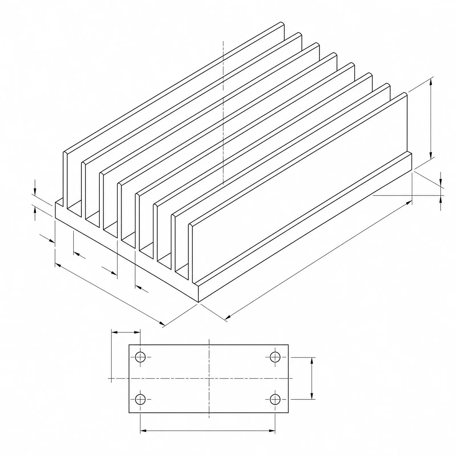 Fin architecture: extrudedBase length: 120mmBase width: 80mmBase thickness: 6mmFin height: 30mm
Concept dimensions guide the prompt and visual only; they are not manufacturable CAD geometry or production drawings.
Configure a heatsink drawing
More parameters
Texto de referencia generado
Create a dimensioned CAD-style technical drawing of a heatsink, with coherent orthographic and isometric views, visible fin pitch, base thickness, mounting holes, and clear leader dimensions. extruded aluminum heatsink with straight parallel fins drafted 1 degree per side and a continuous base. Base length: 120mm. Base width: 80mm. Base thickness: 6mm. Fin height: 30mm. Fin pitch: 5.5mm. sized for forced air from an axial fan, with the fan footprint and airflow direction arrows along the fin channels. four M4 clearance holes at the base corners with 8 mm edge distance and counterbores on the fin side.
Heatsink CAD-style examples
Preguntas frecuentes
Can DrawCAD calculate thermal resistance?
No. The image communicates fin geometry and proportions, but the actual degrees C per watt depends on airflow, material conductivity, interface resistance, and mounting pressure. Get that number from a thermal solver or a bench test.
How do I show fin pitch clearly?
Ask for an end or section view and state fin count, fin thickness, and center-to-center pitch. A top view on its own tends to flatten the fin channels and hide the spacing.
Can I get an extrusion profile file for tooling?
No. DrawCAD outputs CAD-style images, not editable STEP or DXF profiles or die drawings. Redraw and verify the profile in CAD before quoting an extrusion die.
¿Necesitas más intentos?
Tras la actualización, podrás obtener más puntos, una resolución más alta y la posibilidad de exportar archivos sin marca de agua.