
Gear CAD Drawing Generator
Turn tooth count, pitch, bore, hub, keyway, and gear-family details into CAD-style gear images for mechanism concepts, teaching materials, and technical presentations.
Output: CAD-style PNG · Not an editable CAD file
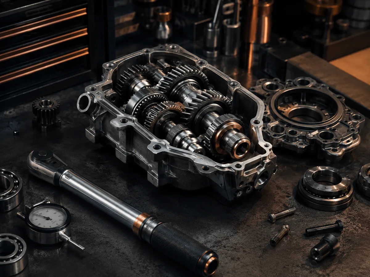
How to generate a gear drawing
Gear drawing prompts
Use a prompt for a spur gear, pulley, bevel pair, or worm wheel, then replace the tooth and shaft details.
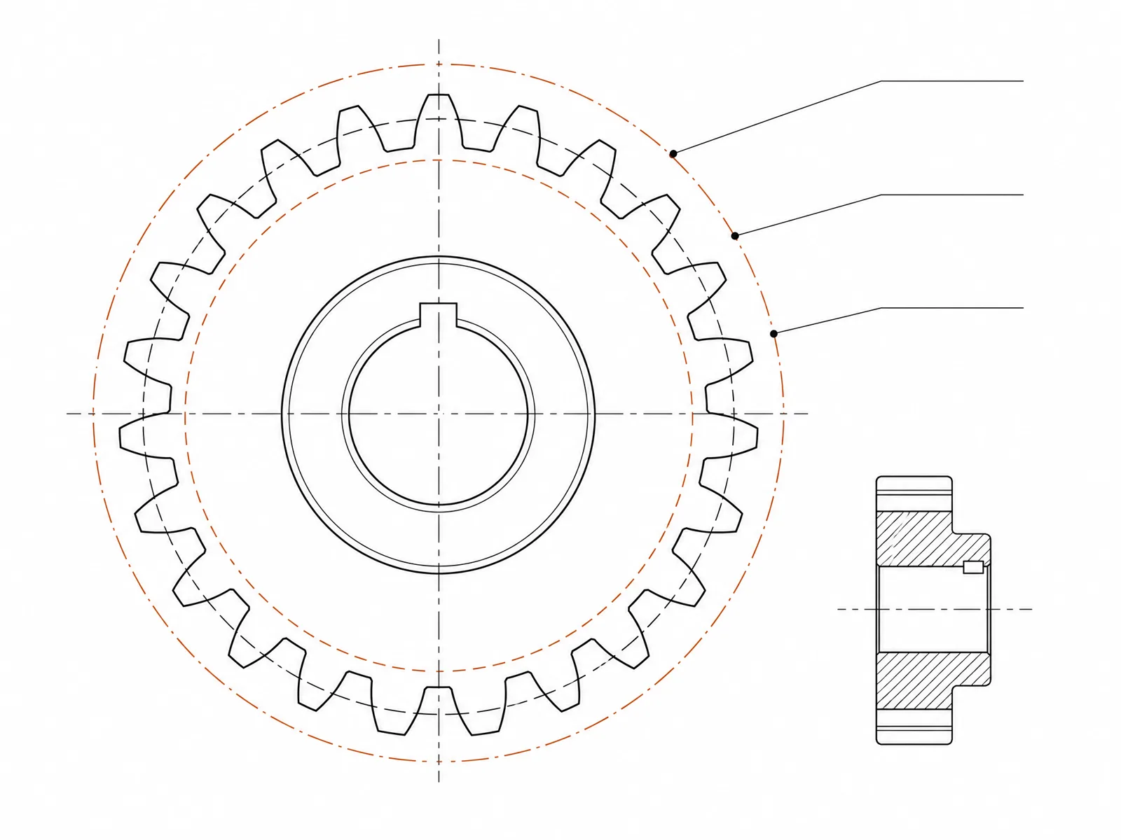 Gear type: spurTooth count: 24teethNormal module: 2.5mmFinished bore: 12mmFace width: 20mm
Concept dimensions guide the prompt and visual only; they are not manufacturable CAD geometry or production drawings.
Configure a gear drawing
More parameters
Generated prompt
Create a dimensioned CAD-style technical drawing of a gear concept, showing the pitch circle, bore and hub geometry, tooth count callout, and coherent front, section, and isometric views. external involute spur gear with straight teeth. Tooth count: 24teeth. Normal module: 2.5mm. Finished bore: 12mm. Face width: 20mm. raised cylindrical hub with a standard parallel keyway and hub-length dimension.
Gear CAD-style examples
FAQ
Are the generated teeth mathematically accurate?
Not necessarily. Image generation can illustrate tooth form and proportions, but it does not replace involute calculations or a gear-design tool.
Can I visualize two gears in mesh?
Yes. State both tooth counts, the shaft relationship, center distance, and request an assembly or exploded view.
Can I export this gear as STEP or STL?
No. DrawCAD creates CAD-style images rather than editable or manufacturing-grade STEP/STL models. Build and verify the final gear in mechanical CAD software.
Need more renders?
Upgrade for more credits, higher resolution, and watermark-free exports.