
Flange CAD Drawing Generator
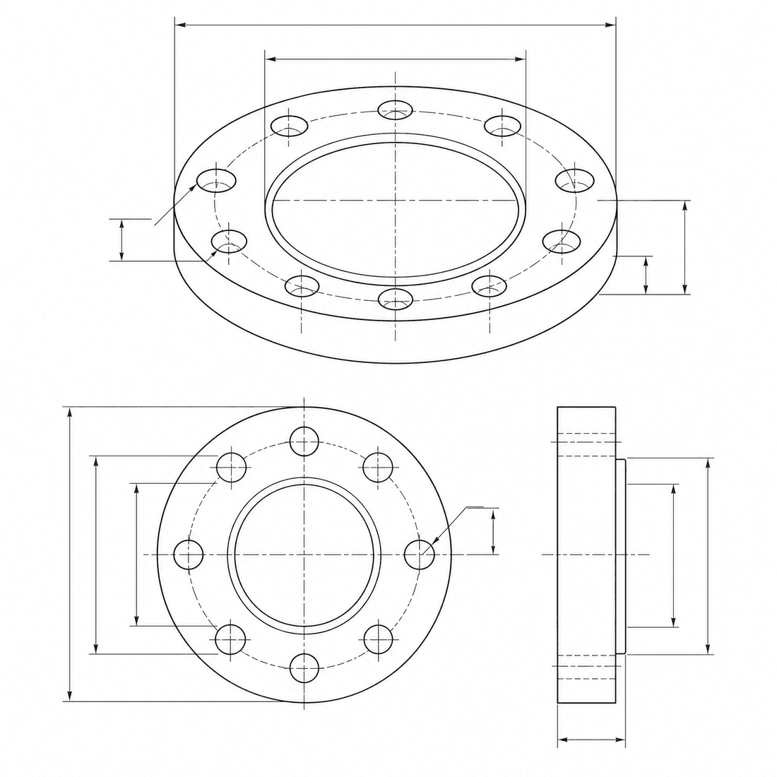
Describe a pipe, motor, weld-neck, or clamp flange with its bore, bolt circle, face, and hub geometry. DrawCAD produces a CAD-style image for visual planning and communication.
출력: CAD 스타일 PNG · 편집 불가능한 CAD 파일

How to generate a flange drawing
Flange drawing prompts
Choose a flange construction, then set its main diameters, hole pattern, sealing face, and preferred technical view.
 Flange type: raised-faceOutside diameter: 120mmBore diameter: 55mmFlange thickness: 16mmBolt count: 6holes
Concept dimensions guide the prompt and visual only; they are not manufacturable CAD geometry or production drawings.
Configure a flange drawing
More parameters
생성된 프롬프트
Create a dimensioned CAD-style technical drawing of a flange, with a front view, axial section, isometric view, centerlines, diameter symbols, and a fully defined bolt-circle pattern. circular raised-face pipe flange with a concentric gasket land. Outside diameter: 120mm. Bore diameter: 55mm. Flange thickness: 16mm. Bolt count: 6holes. Bolt-circle diameter: 90mm. Bolt-hole diameter: 11mm.
Flange CAD-style examples
자주 묻는 질문
Can DrawCAD select a standard flange size?
No. You can name a standard for visual context, but pressure class, dimensions, materials, and compliance must be checked against the authoritative specification.
How should I describe a bolt circle?
Include the number of equally spaced holes, each hole diameter, the pitch-circle diameter, and any angular offset from a centerline.
Is the result suitable for flange fabrication?
No. It is a CAD-style image, not a toleranced manufacturing drawing or verified STEP/STL file. Sealing, pressure, and fabrication details require engineering CAD and review.
더 많은 생성 횟수가 필요하신가요?
업그레이드하면 더 많은 포인트, 더 높은 해상도, 워터마크 없는 파일 내보내기 기능을 이용할 수 있습니다.