
散热片 CAD 图生成器
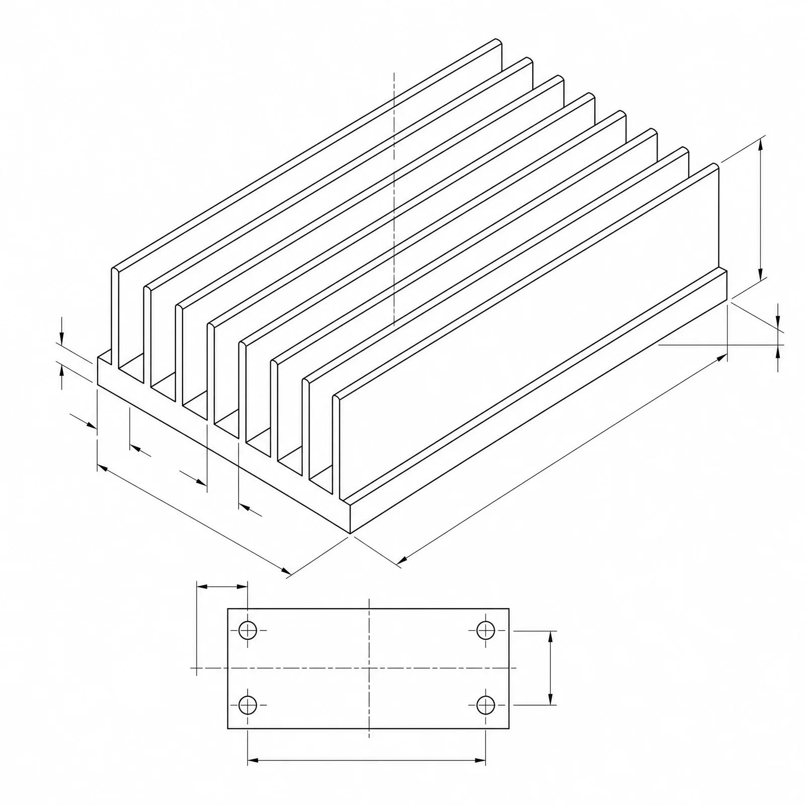
写明翅片间距、翅片高度、基板厚度和安装孔位,DrawCAD 会生成清晰的 CAD 风格散热片图像,适用于散热方案评审、规格书和机箱风道研究。
输出:CAD 风格 PNG · 不是可编辑 CAD 文件
如何生成散热片图
散热片绘图提示词
先选定翅片形式,再替换成自己的底面尺寸、翅片数量、间距和安装接口。
 翅片形式: extruded基板长度: 120mm基板宽度: 80mm基板厚度: 6mm翅片高度: 30mm
概念尺寸仅用于提示词和视觉沟通,不构成可制造 CAD 几何或生产图。
配置散热片图
更多参数
生成的提示词
Create a dimensioned CAD-style technical drawing of a heatsink, with coherent orthographic and isometric views, visible fin pitch, base thickness, mounting holes, and clear leader dimensions. extruded aluminum heatsink with straight parallel fins drafted 1 degree per side and a continuous base. Base length: 120mm. Base width: 80mm. Base thickness: 6mm. Fin height: 30mm. Fin pitch: 5.5mm. sized for forced air from an axial fan, with the fan footprint and airflow direction arrows along the fin channels. four M4 clearance holes at the base corners with 8 mm edge distance and counterbores on the fin side.
散热片 CAD 风格示例
常见问题
DrawCAD 能计算热阻吗?
不能。图像只表达翅片几何和比例,实际 °C/W 取决于风量、材料导热率、界面热阻和安装压力,需要用热仿真或实测得到。
怎样清楚表现翅片间距?
要求端视图或剖视图,并写明翅片数量、翅片厚度和中心距。只给俯视图会把翅片通道压平,看不出间距。
能得到用于开模的型材截面文件吗?
不能。DrawCAD 输出 CAD 风格图像,不是可编辑的 STEP/DXF 截面或模具图。开挤压模前请在 CAD 中重绘并校核截面。
需要更多生成次数?
升级后可获得更多积分、更高分辨率和无水印导出。